Allen Bradley 501 CPU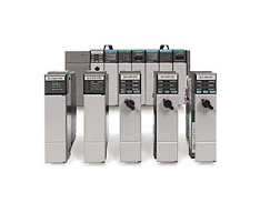
Allen Bradley 502 CPU
Allen Bradley 503 CPU
Allen Bradley 504 CPU
Allen Bradley 505 CPU
Allen Bradley SLC PLC Programming
Allen Bradley SLC Troubleshooting
Allen Bradley SLC Repair
Allen Bradley SLC Replacement Parts
Allen Bradley RS Logix 500, RS Logix 5000, Studio 5000, RS Linx
With have over 20 years of programming experience with the AB SLC PLC family, we have used this family for various applications, from simple machine control to servo applications. The AB SLC was a wildly popular PLC platform and was a direct competitor to the GE 90/30 which was also very, very popular. The SLC family of processors were also referred to as the “SLICK” 500. The “SLICK” referencing the SLC.
With the introduction of the SLC family came the RS Logix 500 programing software. This quickly became the “golden standard” of the PLC programming world due to its intuitive interface and the fact the program “worked with the user” The part number for the Allen Bradley SLC is 1747 for the various CPUs, programming cables and 1746 for the Chassis, I/O modules, power supplies etc.
The SLC family put AB firmly into the smaller platform PLC world as most PLC manufacturers used large platforms which was a limitation of the technology at that time.
Unfortunately, the SLC family of processors suffered from the lack of a common programming cable as was the case with the GE 90/30 and 90/70 family which used the same programming cable. So in order to connect to any of the 5 CPUs you had to have a multiple cables on hand. The most controversial cable being the 1747-PIC interface module, affectionally known to this author as the “pick your nose” module.
There were 5 processor models for the SLC family, with some models having multiple processors. All of the AB processors used “hard & ridged” addressing for internal address and external I/O. Once understood the internal memory types were easy to understand, expandable and highly flexible for the technology at that time.
The SLC family of processors was broken down as follows:
SLC 5/01 Processor
- There are 2 processors within the 5/01 family.
- Catalog No. 1747-L511 with 1K of memory
- Catalog No. 1747-L514 with 4K of memory
- No Floating-point math
- Requires 1747-PIC module for programming.
SLC 5/02 Processor
- There is only one processor within this family.
- Catalog No. 1747-L524 with 4K of memory
- No Floating-point math
- Requires 1747-PIC cable for programming.
SLC 5/03 Processor
- There are 2 processors within this family.
- Catalog No. 1747-L531 with 8K of memory
- Catalog No. 1747-L532 with 16K of memory
- Floating point math along with PID, Trig and a compute expression function block was featured
- Requires a 1747-CP3 Serial cable (RS232) for programming.
- Key switch for mode selection
SLC 5/04 Processor
There are 3 processors within this family
- Catalog No. 1747-L541 with 16K of memory
- Catalog No. 1747-L542 with 32K of memory
- Catalog No. 1747-L543 with 64K of memory
- Real time clock and calendar
- Floating point math along with PID, Trig and a compute expression function block was featured.
- Requires a 1747-CP3 Serial cable (RS232) for programming or OIU/HMI interface or the infamous 1747-PCMK programming cable.
- Key switch for mode selection
The processor featured a round 8 pin port and made connection a bit easier and somewhat faster over it’s serial cousin. However, the cable required a PC with a PCIM card slot. These were somewhat common but had a short life as the USB interface took over.
SLC 5/05 Processor
There are 3 processors within this family
- Catalog No. 1747-L551 with 16K of memory
- Catalog No. 1747-L552 with 32K of memory
- Catalog No. 1747-L553 with 64K of memory
- Floating point math along with PID, Trig and a compute expression function block was featured.
- Ethernet 10Base T Port that use TC/Ip protocol
- High Speed performance
- Real time clock and calendar
- Requires a 1747-CP3 Serial cable (RS232) for programming or OIU/HMI interface or ethernet connectivity.
- Key switch for mode selection
As stated earlier, the I/O modules begin with 1746 and the last part of the part number is the number of I/O points. Example 1746-IA16 is a 16-point ac input module. The I or O stands for input or Output. The designations are as follows:
IA – AC Input Modules 120 VAC
IB – DC Input Modules 24VDC
IM – AC Input Module High Voltage (200-240
IN – Ac Input Module 24VAC
IC – DC Input Module 48 VDC
IH – DC Input Module High Voltage 125VDC
IV – DC Current Sourcing 24VDC
IG – DC Input TTL 5VDC
OA – AC Output Module 120/240VAC
OB – DC Output Module 24VDC
OV – Current Sourcing Output Module 24VDC
OW – Relay Output module 5-265VAC or 5-125VDC
OX – Isolated Relay Output Module
IO – Combo Input Output Module
NI – Analog Input Module
NO – Analog Output Module
NT – Thermocouple/Mv Module
NR – RTD Input Module
HSCE – High Speed Counter Module
HSTP – Stepper Module
There are other designations such as ITV, ITB, BAS, INT, OG, OBP, OAP, OB”XX”E. But the above listing are the most commonly used.